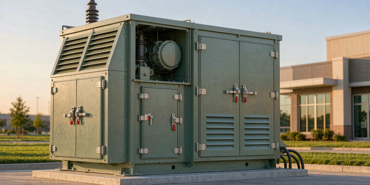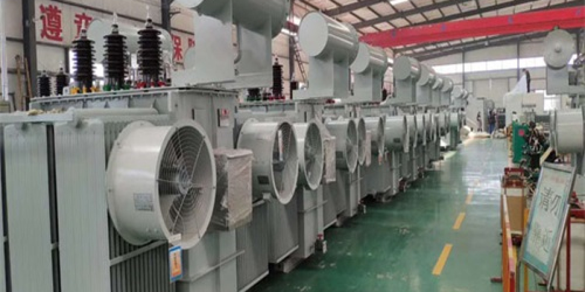

Installing an oil-filled power transformer comes down to seven steps: prep the site and the drawings, rig it without stressing the bushings, set it level on sound foundations with the right rail gauge and a slight tilt for the Buchholz relay, seal every flange, bond the copper-to-aluminum and ground connections to NEC, vacuum-fill the oil, then test and energize. Get any one of those wrong and you trade a clean commissioning for oil leaks, trips, or a unit you have to de-energize and reopen.
1. Before you start: site and document prep
The install goes sideways most often because nobody read the drawings before the truck showed up. Confirm the location matches the approved layout and the unit's ratings, and check that the crane can actually reach the pad — overhead lines, fences, and grade all eat into your swing room.
- Inspect the foundation, anchor bolts, oil containment pit (if the site requires one), and any pad-mounted heater before the transformer arrives. A missing anchor sleeve is a lot cheaper to fix in concrete than after the unit is sitting on it.
- Stage the tools, gaskets, lifting gear, and crew. Pull the rigging plan and the certified lift points from the manufacturer's drawing — not from memory.
- Coordinate with the Authority Having Jurisdiction (AHJ) up front. In the U.S. that means NEC Article 450 for the transformer rules and IEEE C57.12.x for the unit itself, plus whatever your local amendment adds.
The oil-immersed units we build are listed on the products page.
2. Rigging and lifting
Lifting is where transformers get damaged for good. Identify the certified lift points on the tank and use only those. Never rig to the bushings, radiators, or conservator — they are not structural and they crack.
- Size slings, spreader beams, and shackles for the gross weight including oil, and inspect every fitting before the pick.
- Keep the lift angle and speed controlled, hold the unit level, and avoid shock loads and collisions with walls or other equipment.
- In the U.S., the crane work follows ASME B30.5 and the rigging follows OSHA 29 CFR 1926 Subpart CC. A qualified rigger signs off on the plan; nobody else should.
3. Location, foundation, and rails
Put the unit somewhere dry and ventilated, away from corrosive gas and heavy dust, with enough clearance to pull a radiator or open a cabinet later. The environment decides a lot of the maintenance you'll be doing in year five.
- Foundation rails must be level, and the rail gauge has to match the tank wheelbase (or the base mounting holes, for pad-mounted units). A unit sitting on a twisted rail frame stresses the tank seam every thermal cycle.
- For pad-mounted units, the concrete pad has to be level and sound, and the tank base should stay above surface water — the same drainage logic covered in our foundation-height guidance.
- Units fitted with a gas relay (Buchholz) need a 1%–1.5% rise of the top cover along the gas-flow direction toward the relay, unless the manufacturer says otherwise.
Item | What to check | Note |
Environment | Dry, ventilated, non-corrosive, low dust | Drives maintenance burden |
Rails / pad | Level; gauge matches wheelbase or bolt holes | Twist stresses the seam |
Buchholz slope | 1%–1.5% rise toward the relay | Manufacturer may specify otherwise |
Drainage | Tank base above standing water | Ties to pad height |
4. Accessories and sealing
This is the section that decides whether you have a leak in month two. Most field leaks are flange joints, not tank walls.
- When a bushing connects to a bus duct or enclosure, the bushing centerline must line up with the connected centerline. Forced alignment bends the bushing and the seal.
- Units shipped on wheels get removable wheel chocks or brake blocks once they are set in place, so the unit cannot roll during energization or a fault.
- Every flange joint uses an oil-resistant gasket. Keep both faces clean, and where the gasket steps (overlaps), the step thickness should match the gasket thickness so the compression is even.
- Compress rubber gaskets no more than one-third of their thickness. Past that, the rubber takes a set and the joint weeps.
Rule | Why it matters |
Clean both gasket faces | Dirt breaks the seal line |
Step thickness = gasket thickness | Even compression |
Max 1/3 compression | Over-compression cracks the joint |
5. Wiring and grounding
Terminate per the wiring diagram and verify phasing and vector group before you torque anything. If you are not sure what the winding connection does to your phase shift, read our delta-wye transformer guide before the lugs go on.
- Copper-to-aluminum joints use bimetallic (Cu-Al transition) connectors. Bolting raw copper straight to aluminum is a guaranteed hot spot and a future outage; NEC 110.14 expects listed connectors for the mix.
- Grounding has to be solid and the circuits kept separate: the working neutral and the equipment grounding conductor stay independent, and the working neutral is not laid underground as a ground path. Put a disconnectable link in the ground conductor so you can test the ground later without cutting it.
- Size the overcurrent protection with our NEC 450.3(B) transformer calculator; it works through the primary and secondary protection tables for liquid-filled and dry-type units.
6. Cooling and oil filling
Coolers and radiators get flushed with qualified insulating oil through an oil purifier and drained of residual before they go on, then sealed and filled promptly so moisture does not get a chance to enter.
- Fill from the bottom valve — vacuum oil filling where the manufacturer specifies it. Filling from the top lets air pockets sit under the core and radiators.
- Hold the correct oil level and confirm there is no seepage at the new joints before you button it up.
- In U.S. practice, vacuum filling is the norm whenever a unit ships without oil or the tank has been opened for any reason. Follow the manufacturer's vacuum level and hold-time limits; pulling a deeper vacuum than specified can damage the insulation.
7. Inspection and commissioning
Do not energize on hope. Walk the unit, then prove it electrically.
- Visual: tank, bushings, accessories, mounting, and oil level all correct, no leaks at the flanges you just tightened.
- Electrical: insulation resistance (Megger) on each winding to ground and between windings, plus power-factor / dissipation-factor and turns-ratio where the specification calls for them. Compare the field numbers to the factory test report; a big swing means something got wet or damaged in transit.
- After filling, let the oil settle, then take a dissolved gas analysis (DGA) baseline so a future sample has something to compare against. Check for moisture.
- Energize on a staged plan and watch for abnormal sound, temperature, or leaks. Acceptance testing follows IEEE C57.12.90;
We cover testing, vector groups, and commissioning details across the resources library.
8. FAQ
Can I lift an oil transformer by its bushings? No. Lift only at the certified tank lift points. Bushings, radiators, and the conservator are not load paths and will crack or shear, which means a new bushing or a reopened tank before you have even energized.
Why does the top cover need a 1%–1.5% slope? That tilt is for the Buchholz (gas) relay. Gas and air collect at the high point, and the slope steers them toward the relay so it actually sees them and trips instead of letting a fault build unseen.
How tight should the flange gaskets be? Compress them no more than one-third of their thickness. Most field leaks come from over-torqueing, which takes a permanent set in the rubber and opens the seam.
Do I really need bimetallic connectors for copper-to-aluminum? Yes. Bolting bare copper to aluminum forms a galvanic couple that runs hot and fails. Use listed Cu-Al transition connectors, per NEC 110.14. It is a small part that prevents a large outage.
Can the working neutral double as a ground? No. Keep the working neutral and the equipment grounding conductor separate, and do not bury the working neutral as a ground path. Provide a disconnectable link in the ground conductor so it can be tested without being cut.
Should the transformer be vacuum-filled with oil on site? If the unit shipped without oil, or the tank was opened for any reason, vacuum filling is the standard U.S. practice. Follow the manufacturer's vacuum level and hold time — pulling too deep a vacuum can damage the insulation.
What tests prove it is ready to energize? A visual check for leaks and correct oil level, a Megger insulation-resistance test on each winding, power-factor and turns-ratio where specified, and a DGA baseline after the oil settles. Acceptance testing follows IEEE C57.12.90.